TSHOOT
Exam’s Structure:
+ About 10 Multichoice questions
+ 2 Drag and Drop Questions
+ 16 lab-sim Questions with the same network topology (16 troubleshooting tickets or you can call it one “big” question). Each lab-sim is called a ticket and you can solve them in any order you like.
+ 2 Drag and Drop Questions
+ 16 lab-sim Questions with the same network topology (16 troubleshooting tickets or you can call it one “big” question). Each lab-sim is called a ticket and you can solve them in any order you like.
Topics of the lab-sims:
1 -IPv6
2 -OSPF
3- OSPFv3
4 -Frame Relay
5 – GRE
6 – EtherChannel
7 -RIPng
8 -EIGRP
9 -Redistribution
10 -NTP
11 -NAT
12 -BGP
13 -HSRP
14-STP
15-DHCP
2 -OSPF
3- OSPFv3
4 -Frame Relay
5 – GRE
6 – EtherChannel
7 -RIPng
8 -EIGRP
9 -Redistribution
10 -NTP
11 -NAT
12 -BGP
13 -HSRP
14-STP
15-DHCP
The problems are rather simple. For example wrong IP assignment, disable or enable a command, authentication…
In each tickets you will have to answers three types of questions:
+ Which device causes problem
+ Which technology is used
+ How to fix it
+ Which technology is used
+ How to fix it
When you press Done to finish each case, you can’t go back.
A demo of the TSHOOT Exam can be found at:http://www.cisco.com/web/learning/le3/le2/le37/le10/tshoot_demo.html
IPv4 Layer 3 Topology

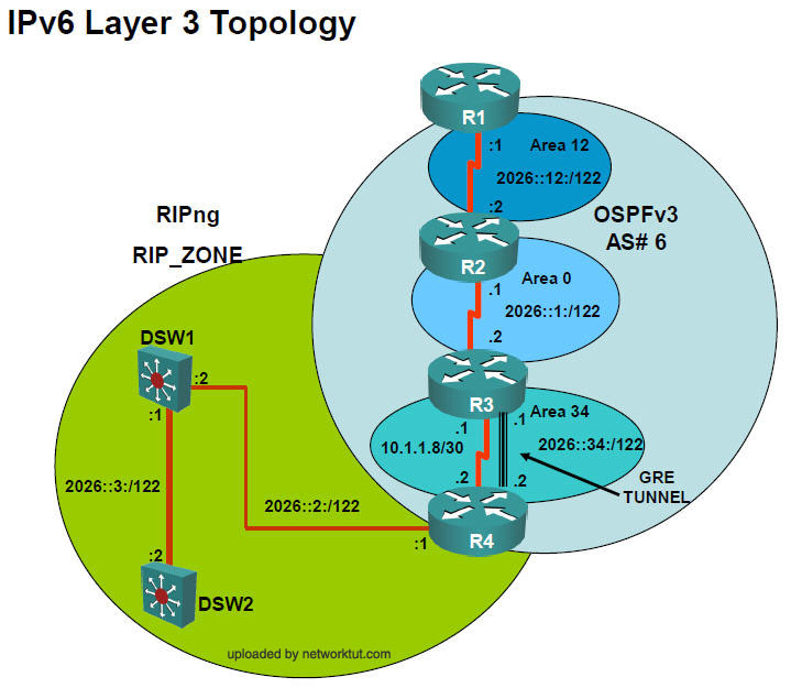
IPv6 Layer 3 Topology
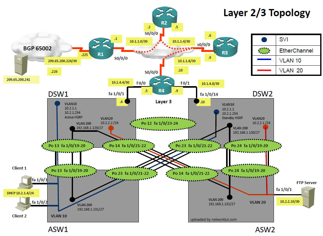
Layer 2-3 Topology
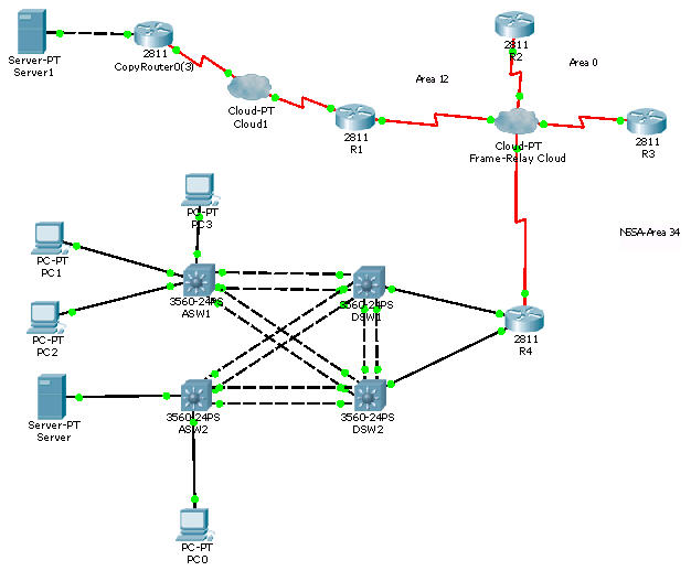
Luckily we have a link to download this lab (open it with Packet Tracer v.5.3+)
Below is the screenshot of this file
Question 1
FCAPS
Fault Management ‐‐‐‐‐‐‐‐‐‐‐‐‐‐‐‐‐ F
Configuration Management ‐‐‐‐‐‐‐ C
Accounting Management ‐‐‐‐‐‐‐‐‐‐ A
Fault Management ‐‐‐‐‐‐‐‐‐‐‐‐‐‐‐‐‐ F
Configuration Management ‐‐‐‐‐‐‐ C
Accounting Management ‐‐‐‐‐‐‐‐‐‐ A
Question 2
FCAPS–model defined by the International Organization for Standardization (ISO).
ITIL– framework for it prof
TNM–network management model is the Telecommunications Standardization Sector’s (ITU-T)
Cisco lifecycle–model is often referred to as the PPDIOO model
ITIL– framework for it prof
TNM–network management model is the Telecommunications Standardization Sector’s (ITU-T)
Cisco lifecycle–model is often referred to as the PPDIOO model
Question 3
EEM ‐‐‐‐‐‐‐‐‐‐‐‐‐‐ CLI based for Management and Monitoring
SDM ‐‐‐‐‐‐‐‐‐‐‐‐‐‐ provide a GUI for Administration
FTP ‐‐‐‐‐‐‐‐‐‐‐‐‐‐ Used for Backup and restore
SDM ‐‐‐‐‐‐‐‐‐‐‐‐‐‐ provide a GUI for Administration
FTP ‐‐‐‐‐‐‐‐‐‐‐‐‐‐ Used for Backup and restore
-----------------------------------------------------------------------------------------------------------------------------------
1)FCAPS is a network maintenance model defined by ISO. What does it stand for?
A – Action Management
B – Fault Management
C – Configuration Management
D – Protocol Management
E – Security Management
B – Fault Management
C – Configuration Management
D – Protocol Management
E – Security Management
Answer: B C E (Fault, Configuration & Security Management) Notice that A stands for Accounting, not Action.
2) Which alerts will be seen on the console when running the command: logging console warnings.
A – warnings only
B – warnings, notifications, error, debugging, informational
C – warnings, errors, critical, alerts, emergencies
D – notifications, warnings, errors
E – warnings, errors, critical, alerts
B – warnings, notifications, error, debugging, informational
C – warnings, errors, critical, alerts, emergencies
D – notifications, warnings, errors
E – warnings, errors, critical, alerts
Answer: C (warning, critical, alert, emergencies)
Explanation
The Message Logging is divided into 8 levels as listed below
| Level | Keyword | Description |
| 1 | alerts | |
| 2 | critical | |
| 3 | ||
| 4 | ||
| 5 | ||
| 6 | ||
| 7 |
3) You have 2 commands used for ftp:
ip ftp username xxxxxx
ip ftp password yyyyyy
ip ftp username xxxxxx
ip ftp password yyyyyy
Which two commands will be used when switching from ftp to http?
Answer:
ip http client username xxxxxx
ip http client password yyyyyy
ip http client username xxxxxx
ip http client password yyyyyy
4) Which two of the following options are categories of Network Maintenance tasks?
A – Firefighting
B – Interrupt-driven
C – Policy-based
D – Structured
E – Foundational
B – Interrupt-driven
C – Policy-based
D – Structured
E – Foundational
Answer: B D
5) The following commands are issued on a Cisco router:
Router(config)#access-list 199 permit tcp host 10.1.1.1 host 172.16.1.1
Router(config)#access-list 199 permit tcp host 172.16.1.1 host 10.1.1.1
Router#debug ip packet 199
Router(config)#access-list 199 permit tcp host 172.16.1.1 host 10.1.1.1
Router#debug ip packet 199
What would be the output shown on the console?
A – All IP packets passing through the router
B – Only IP packets with the source address of 10.1.1.1
C – All IP packets from 10.1.1.1 to 172.16.1.1
D – All IP packets between 10.1.1.1 to 172.16.1.1
B – Only IP packets with the source address of 10.1.1.1
C – All IP packets from 10.1.1.1 to 172.16.1.1
D – All IP packets between 10.1.1.1 to 172.16.1.1
Answer: D
Only communication between host 10.1.1.1 and host 172.16.1.1
6) You have two NTP servers 10.1.1.1 & 10.1.1.2 and want to configure a router to use 10.1.1.2 as its NTP server before falling back to 10.1.1.1. Which command will you use?
Answer:
ntp server 10.1.1.1
ntp server 10.1.1.2 prefer
ntp server 10.1.1.2 prefer
(notice the answer with the word “prefer”)
7) The interface is up and protocol is up. What level of logging is enabled when you get these messages?
%LINEPROTO‐5‐UPDOWN: Line protocol on Interface FastEthernet0/1, changed state to up
%LINKDOWN‐3‐SERIAL:
%LINKDOWN‐3‐SERIAL:
A -alerts
B – errors
C – critical
D – notifications
B – errors
C – critical
D – notifications
Answer: D
8) Two Cisco routers are connected to each other and are enabled CDP. Serial line is up,protocol is also up but cdp neighbor not working. What layer of the OSI model does the problem most likely exist?
Answer:
Data link layer.
-------------------------------------------------------------------------------------------------------------------------------
Ticket 1 – OSPF Authentication
1.Client is unable to ping R1’s serial interface from the client.
Problem was disable authentification on R1, check where authentication is not given under router ospf of R1. (use ipv4 Layer 3)
Configuration on R1 was:
interface Serial0/0/0/0.12 point-to-point
ip address 10.1.1.1 255.255.255.252
ip nat inside
ip ospf message-digest-key 1 md5 TSHOOT
!
router ospf 1
log-adjacency-changes
network 10.1.1.0 0.0.0.3 area 12
default-information originate always
ip address 10.1.1.1 255.255.255.252
ip nat inside
ip ospf message-digest-key 1 md5 TSHOOT
!
router ospf 1
log-adjacency-changes
network 10.1.1.0 0.0.0.3 area 12
default-information originate always
Configuration on R2 was:
interface Serial0/0/0/0.12 point-to-point
ip address 10.1.1.2 255.255.255.252
ip ospf authentication message-digest
ip ospf message-digest-key 1 md5 TSHOOT
!
router ospf 1
log-adjacency-changes
network 10.1.1.0 0.0.0.3 area 12
interface Serial0/0/0/0.12 point-to-point
ip address 10.1.1.2 255.255.255.252
ip ospf authentication message-digest
ip ospf message-digest-key 1 md5 TSHOOT
!
router ospf 1
log-adjacency-changes
network 10.1.1.0 0.0.0.3 area 12
Answer: on R1 need command in router mode
area 12 authentication message-digest
area 12 authentication message-digest
Ans1) R1
Ans2) OSPF
Ans3) ip ospf authentication message-digest command must be given on s0/0/0/0.12
Ans2) OSPF
Ans3) ip ospf authentication message-digest command must be given on s0/0/0/0.12
-------------------------------------------------------------------------------------------------------------------------------
Ticket 2 – HSRP Track
HSRP was configured on DSW1 & DSW2. DSW1 is configured to be active but it does not become active.
Configuration on DSW1:
track 1 ip route 10.1.21.128 255.255.0.0 metric threshold
threshold metric up 1 down 2
!
track 10 ip route 10.2.21.128 255.255.255.0 metric threshold
threshold metric up 63 down 64
!
threshold metric up 1 down 2
!
track 10 ip route 10.2.21.128 255.255.255.0 metric threshold
threshold metric up 63 down 64
!
interface Vlan10
ip address 10.2.1.1 255.255.255.0
standby 10 ip 10.2.1.254
standby 10 priority 200
standby 10 preempt
standby 10 track 1 decrement 60
ip address 10.2.1.1 255.255.255.0
standby 10 ip 10.2.1.254
standby 10 priority 200
standby 10 preempt
standby 10 track 1 decrement 60
Answer: (use IPv4 Layer 3 Topology)
On dsw 1 interface vlan 10 mode run:
no standby 10 track 1 decrement 60
standby 10 track 10 decrement 60
(ip for track command not exact for real exam)
no standby 10 track 1 decrement 60
standby 10 track 10 decrement 60
(ip for track command not exact for real exam)
Ans1) DSW1
Ans2) HSRP
Ans3) delete the command with track 1 and enter the command with track 10 (standby 10 track 10 decrement 60).
Ans2) HSRP
Ans3) delete the command with track 1 and enter the command with track 10 (standby 10 track 10 decrement 60).
---------------------------------------------------------------------------------------------------------------------------------
Ticket 3 – BGP Neighbor
Problem: Client 1 is able to ping 209.65.200.226 but can’t ping the Web Server 209.65.200.241.
Configuration on R1:
router bgp 65001
no synchronization
bgp log-neighbor-changes
network 209.65.200.224 mask 255.255.255.252
neighbor 209.56.200.226 remote-as 65002
no auto-summary
router bgp 65001
no synchronization
bgp log-neighbor-changes
network 209.65.200.224 mask 255.255.255.252
neighbor 209.56.200.226 remote-as 65002
no auto-summary
check bgp neighborship. **** show ip bgp sum****
The neighbor’s address in the neighbor command is wrong under router BGP. (use ipv4 Layer 3)
The neighbor’s address in the neighbor command is wrong under router BGP. (use ipv4 Layer 3)
Answer: need change on router mode on R1 neighbor 209.65.200.226
Ans1) R1
Ans2) BGP
Ans3) delete the wrong neighbor statement and enter the correct neighbor address in the neighbor command (change “neighbor 209.56.200.226 remote-as 65002″ to “neighbor 209.65.200.226 remote-as 65002″)
Ans2) BGP
Ans3) delete the wrong neighbor statement and enter the correct neighbor address in the neighbor command (change “neighbor 209.56.200.226 remote-as 65002″ to “neighbor 209.65.200.226 remote-as 65002″)
---------------------------------------------------------------------------------------------------------------------------------
Ticket 4 – NAT ACL
Client 1 & 2 are not able to ping the web server 209.65.200.241, but all the routers & DSW1,2 can ping the server.
NAT problem. (use ipv4 Layer 3)
problem on R1 Nat acl
problem on R1 Nat acl
Configuration on R1
ip nat inside source list nat_pool interface s0/0/0/1 overload
ip nat inside source list nat_pool interface s0/0/0/1 overload
ip access-list standard nat_pool
permit 10.1.0.0
!
interface serial0/0/0/1
ip address 209.65.200.224 255.255.255.252
ip nat outside
!
interface Serial0/0/0/0.12
ip address 10.1.1.1 255.255.255.252
ip nat inside
ip ospf message-digest-key 1 md5 TSHOOT
ip ospf authentication message-digest
permit 10.1.0.0
!
interface serial0/0/0/1
ip address 209.65.200.224 255.255.255.252
ip nat outside
!
interface Serial0/0/0/0.12
ip address 10.1.1.1 255.255.255.252
ip nat inside
ip ospf message-digest-key 1 md5 TSHOOT
ip ospf authentication message-digest
Answer:add to acl 1 permit ip 10.2.1.0 0.0.0.255
Ans1) R1
Ans2) NAT
Ans3) Add the command permit 10.2.0.0 in the nat_pool access-list
Ans2) NAT
Ans3) Add the command permit 10.2.0.0 in the nat_pool access-list
------------------------------------------------------------------------------------------------------------------------
Ticket 5 – R1 ACL
Client is not able to ping the server. Except for R1, no one else can ping the server. (use ipv4 Layer 3)
Problem:on R1 acl blocking ip
Configuration on R1
Configuration on R1
router bgp 65001
no synchronization
bgp log-neighbor-changes
network 209.65.200.224 mask 255.255.255.252
no synchronization
bgp log-neighbor-changes
network 209.65.200.224 mask 255.255.255.252
neighbor 209.65.200.226 remote-as 65002
no auto-summary
!
access-list 30 permit host 209.65.200.241
access-list 30 deny 10.1.0.0 0.0.255.255
access-list 30 deny 10.2.0.0 0.0.255.255
!
interface Serial0/0/0/1
ip address 209.65.200.224 255.255.255.252
ip nat outside
no auto-summary
!
access-list 30 permit host 209.65.200.241
access-list 30 deny 10.1.0.0 0.0.255.255
access-list 30 deny 10.2.0.0 0.0.255.255
!
interface Serial0/0/0/1
ip address 209.65.200.224 255.255.255.252
ip nat outside
ip access-group 30 in
Answer: add permit 209.65.200.224 0.0.0.3 command to R1′s ACL
Ans1) R1
Ans2) IP Access list
Ans3) Add permit 209.65.200.224 0.0.0.3 to R1′s ACL
Ans2) IP Access list
Ans3) Add permit 209.65.200.224 0.0.0.3 to R1′s ACL
--------------------------------------------------------------------------------------------------------------------------------
Ticket 6 – VLAN filter
Client 1 is getting the correct IP address from DHCP but Client 1 is not able to ping the server. Unable to ping DSW1 or the FTP Server(Use L2 Diagram).
Vlan Access map is applied on DSW1 blocking the ip address of client 10.2.1.3
Configuration on DSW1
vlan access-map test1 10
drop
match ip address 10
!
vlan filter test1 vlan-list 10
!
ip access-list standard 10
permit 10.2.0.0 0.0.255.255
!
interface VLAN10
ip address 10.2.1.1 255.255.255.0
Configuration on DSW1
vlan access-map test1 10
drop
match ip address 10
!
vlan filter test1 vlan-list 10
!
ip access-list standard 10
permit 10.2.0.0 0.0.255.255
!
interface VLAN10
ip address 10.2.1.1 255.255.255.0
Ans1) DSW1
Ans2) Vlan access map
Ans3)Remove vlan filter test1 from DSW1
Ans2) Vlan access map
Ans3)Remove vlan filter test1 from DSW1
---------------------------------------------------------------------------------------------------------------------------------
Ticket 7 – Port Security
Client 1 is getting a 169.x.x.x IP address & is unable to ping Client 2 as well as DSW1. The command ‘sh interfaces fa1/0/1′ will show following message in the first line
‘enFastEthernet1/0/1 is down, line protocol is down (err-disabled)’
‘enFastEthernet1/0/1 is down, line protocol is down (err-disabled)’
On ASW1 port-security mac 0000.0000.0001, interface in err-disable state
Configuration of ASW1
interface fa1/0/1
switchport mode access
switchport port-security
switchport port-security mac-address 0000.0000.0001
interface fa1/0/1
switchport mode access
switchport port-security
switchport port-security mac-address 0000.0000.0001
Answer:on asw1 delele portsecurity & do on interfaces shutdown, no shutdown
Ans1)ASW1
Ans2)Port security
Ans3)issue “no switchport port-security mac-address 0000.0000.0001 command followed by shutdown & no shutdown commands on port fa1/0/1 on ASW1
Ans2)Port security
Ans3)issue “no switchport port-security mac-address 0000.0000.0001 command followed by shutdown & no shutdown commands on port fa1/0/1 on ASW1
---------------------------------------------------------------------------------------------------------------------------------
Ticket 8 – Switchport VLAN 10
Client 1 & 2 are getting 169.x.x.x ip addresses and can’t ping DSW1 or FTP Server but they are able to ping each other.
Situation: in port channel configuration of ASW1 vlan 10 is not allowed. (Use L2 Diagram)
Configuration of ASW1
interface FastEthernet1/0/1
switchport mode access
switchport access vlan 1
!
interface FastEthernet1/0/2
switchport mode access
switchport access vlan 1
Configuration of ASW1
interface FastEthernet1/0/1
switchport mode access
switchport access vlan 1
!
interface FastEthernet1/0/2
switchport mode access
switchport access vlan 1
On ASW1, on interfaces fa0/1, fa0/2 switchport access vlan 1
Answer: on ASW1 change switchport access vlan 1 to switchport access vlan 10
Ans1)ASW1
Ans2)Vlan
Ans3)give command: interface range fa1/0/1-/2 & switchport access vlan 10
Ans2)Vlan
Ans3)give command: interface range fa1/0/1-/2 & switchport access vlan 10
------------------------------------------------------------------------------------------------------------------------------
Ticket 9 – Switchport trunk
Client 1 is getting 169.x.x.x ip address.
Client 1 & 2 can ping each other but they are unable to ping DSW1 or FTP Server (Use L2/3 Diagram)
Configuration of ASW1
interface PortChannel13
switchport mode trunk
switchport trunk allowed vlan 1-9
!
interface PortChannel23
switchport mode trunk
switchport trunk allowed vlan 1-9
!
interface FastEthernet1/0/1
switchport mode access
switchport access vlan 10
!
interface FastEthernet1/0/2
switchport mode access
switchport access vlan 10
Answer: on port channel 13, 23 disables all vlans and give switchport trunk allowed vlan 10,200
Ans1)ASW1
Ans2)Switch to switch connectivity
Ans3)int range portchannel13,portchannel23
switchport trunk allowed vlan none
switchport trunk allowed vlan 10,200
Ans2)Switch to switch connectivity
Ans3)int range portchannel13,portchannel23
switchport trunk allowed vlan none
switchport trunk allowed vlan 10,200
----------------------------------------------------------------------------------------------------------------------------
Ticket 10 – EIGRP AS
Client 1 is not able to ping the Webserver
DSW1 can ping fa0/1 of R4 but can’t ping s0/0/0/0.34
DSW1 can ping fa0/1 of R4 but can’t ping s0/0/0/0.34
Check ip eigrp neighbors from DSW1 you will not see R4 as neighbor.(use ipv4 Layer 3)
‘Show ip route’ on DSW1 you will not see any 10.x.x.x network route.
‘Show ip route’ on DSW1 you will not see any 10.x.x.x network route.
On DSW1 & DWS2 the EIGRP AS number is 10 (router eigrp 10) but on R4 it is 1 (router eigrp 1)
Answer: change router AS on R4 from 1 to 10
Ans1) R4
Ans2) EIGRP
Ans3) Change EIGRP AS number from 1 to 10
Ans2) EIGRP
Ans3) Change EIGRP AS number from 1 to 10
----------------------------------------------------------------------------------------------
Ticket 11 – EIGRP to OSPF
Client 1 is not able to ping the Webserver
DSW1 can ping fa0/1 of R4. However clients and DSW1 can’t ping R4′s S0/0/0/0.34 interface (10.1.1.10)
DSW1 can ping fa0/1 of R4. However clients and DSW1 can’t ping R4′s S0/0/0/0.34 interface (10.1.1.10)
On R4 in router eigrp:
router eigrp 10
network 10.1.4.5 0.0.0.0
no auto-summary
redistribute ospf 1 metric 100 10 255 1 1500 route-map EIGRP_to_OSPF
!
router ospf 1
network 10.1.1.8 0.0.0.0 area 34
redistribute eigrp 10 subnets
!
router eigrp 10
network 10.1.4.5 0.0.0.0
no auto-summary
redistribute ospf 1 metric 100 10 255 1 1500 route-map EIGRP_to_OSPF
!
router ospf 1
network 10.1.1.8 0.0.0.0 area 34
redistribute eigrp 10 subnets
!
route-map EIGRP->OSPF
match ip address 1
match ip address 1
Answer:change in router eigrp router-map name
Ans1) R4
Ans2) Route redistribution
Ans3) Change the name of the route-map under the router EIGRP or router OSPF process from ‘EIGRP_to_OSPF’ to ‘EIGRP->OSPF’.
Ans2) Route redistribution
Ans3) Change the name of the route-map under the router EIGRP or router OSPF process from ‘EIGRP_to_OSPF’ to ‘EIGRP->OSPF’.
----------------------------------------------------------------------------------------------
Ticket 12 – IPv6 OSPF
DSW1 & R4 can’t ping R2′s loopback interface or s0/0/0/0.12 IPv6 address.
R2 is not an OSPFv3 neighbor on R3
Situation: ipv6 ospf was not enabled on R2’s serial interface connecting to R3. (use ipv6 Layer 3)
R2 is not an OSPFv3 neighbor on R3
Situation: ipv6 ospf was not enabled on R2’s serial interface connecting to R3. (use ipv6 Layer 3)
Configuration of R2
ipv6 router ospf 6
router-id 2.2.2.2
!
interface s0/0/0/0.23
ipv6 address 2026::1:1/122
ipv6 router ospf 6
router-id 2.2.2.2
!
interface s0/0/0/0.23
ipv6 address 2026::1:1/122
Configuration of R3
ipv6 router ospf 6
router-id 3.3.3.3
!
interface s0/0/0/0.23
ipv6 address 2026::1:2/122
ipv6 ospf 6 area 0
ipv6 router ospf 6
router-id 3.3.3.3
!
interface s0/0/0/0.23
ipv6 address 2026::1:2/122
ipv6 ospf 6 area 0
Answer:
In interface configuration mode of s0/0/0/0.23 on R2:
ipv6 ospf 6 area 12
ipv6 ospf 6 area 12
Ans1) R2
Ans2) OSPFv3
Ans3) on the serial interface of R2, enter the command ipv6 ospf 6 area 0 (notice that it is “area 0″, not “area 12″)
Ans2) OSPFv3
Ans3) on the serial interface of R2, enter the command ipv6 ospf 6 area 0 (notice that it is “area 0″, not “area 12″)
YOUR TSHOOT EXPERIENCE
The TSHOOT 642-832 exam has been used to replace the old ISCW & ONT exams so this article is devoted for candidates who took this exam sharing their experience.